EngiMetric
From Engineering
Calculations to
Connected Design.
Every figure traceable to its inputs, assumptions, and stated limits.
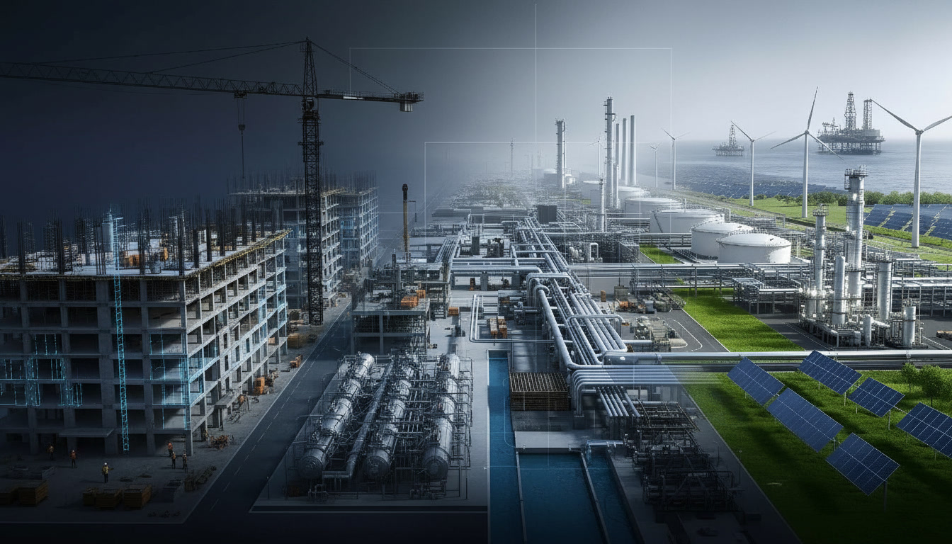
An engineering workspace for solving problems, evaluating alternatives, and connecting calculations to practical design decisions — across Water & Desalination, Construction, Wastewater, and beyond.
Preliminary design support, not an approval. Every figure is labelled stated, derived, or not quantified — nothing is assumed on your behalf.
The engineering path
Every figure carries its basis — stated · derived · not quantified
- 01 Learn principles
- 02 Calculate duty
- 03 Understand driver
- 04 Design process train
- 05 Engineer schedule
- 06 Deliver BoQ · report
Each stage takes the previous stage’s output as its input. Six stages from a water quality to a scheduled, costed, reportable plant — and the same spine whether you are designing a desalination train, sizing an aeration basin, or quantifying a concrete frame.
Flagship products
Three ways to engage the platform.
A challenge to test your reasoning, a workflow to track a project, and a designer to configure a treatment process — each built on the same calculation engines.
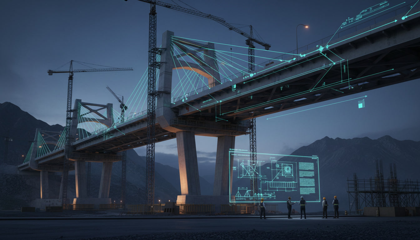 EngiMetric Arena
Engineering challenges you can defend
Real engineering problems — a review finding, a design decision, a trade-off — graded by the same engines that power the calculators. Wrong answers get the reasoning, not just a mark.
Enter the Arena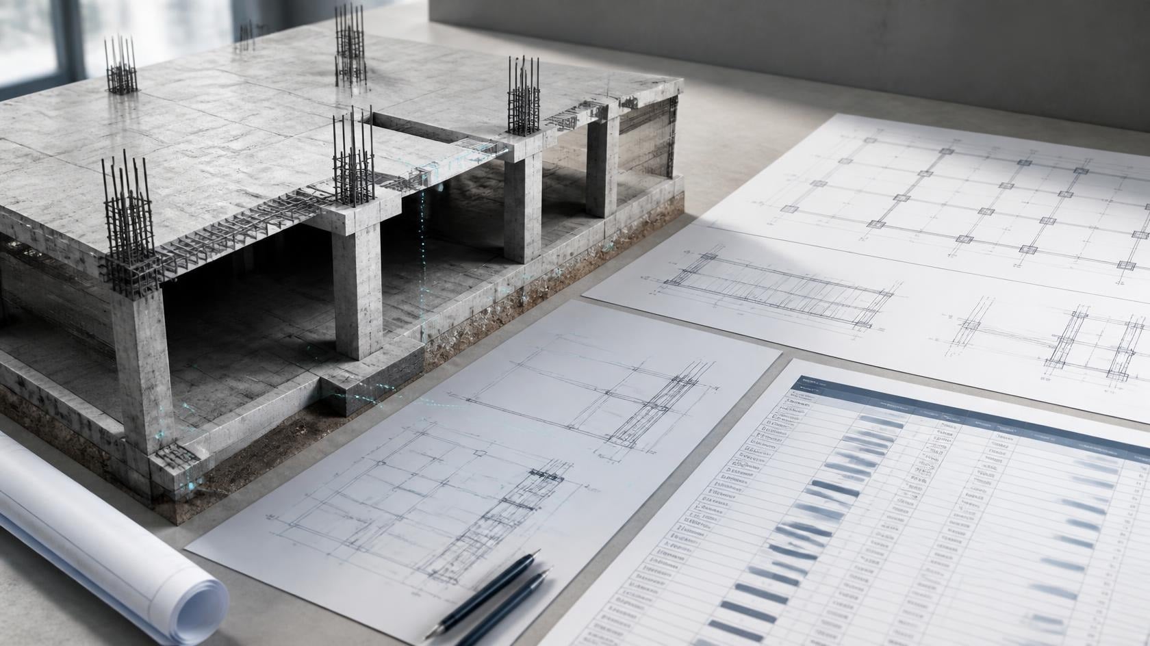 Construction Workflow
Project workflow for construction engineers
Connect site engineering tasks into a traceable project record. Quantities, estimates, interim payments, and site coordination in a single workflow — no separate tools required.
Open Construction Workflow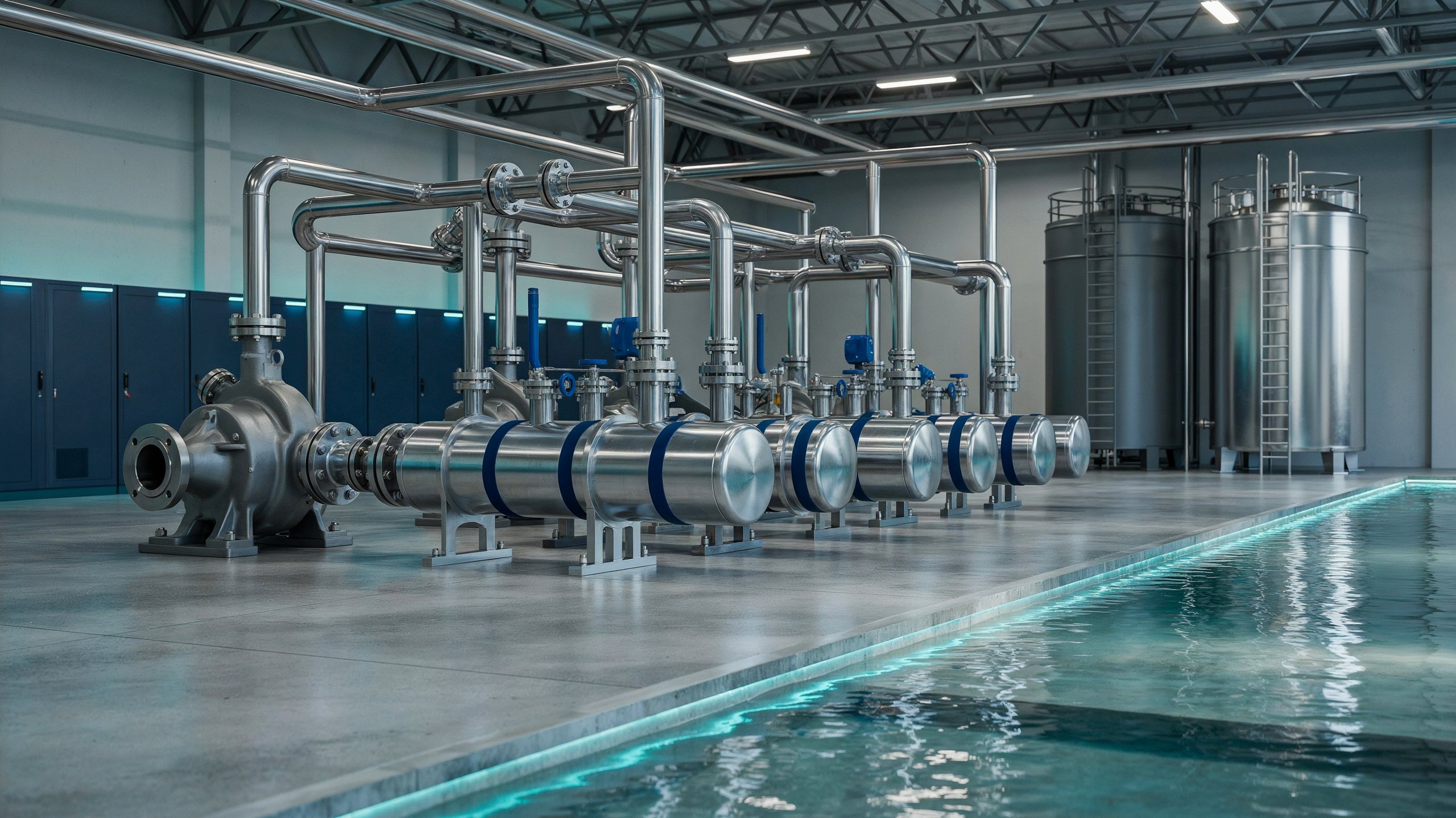 Plant Designer
Desalination & water treatment design
State the product you must produce. The Designer derives the intake, checks the source, balances water and salt across the train, and carries the result to a schedule, BOQ and traceable report.
Open Plant DesignerFlagship product
Where the chain becomes a plant.
State the product you must produce. The Designer derives the intake, checks the source, analyses the feedwater, balances water and salt across the train, hands duty to the equipment layer, and carries it to a schedule, a bill of quantities and a traceable report.
Every stage shows its real state, and every value is labelled stated, derived or not quantified. An unpriced BOQ line stays unpriced until you record a real quotation.
Open Plant Designer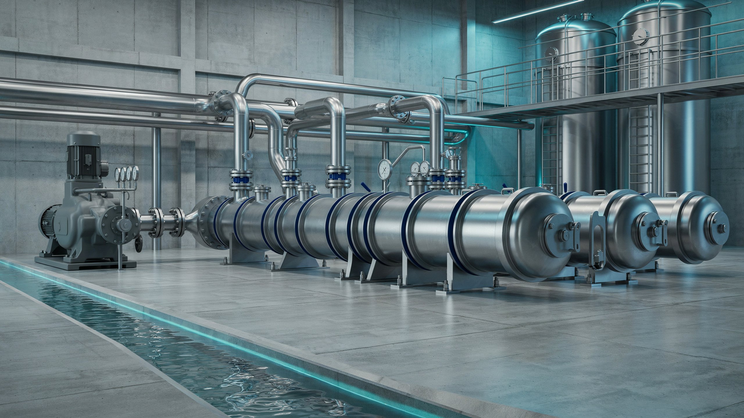
- Treatment train ordered processes, validated stream ports
- Plant mass balance water and salt conservation, closed
- Equipment schedule duty matched to verified candidates
- Bill of quantities quantities, commercial status honest
- Engineering report traceable back to every calculation
- Design basis recovery, rates and demand, all stated
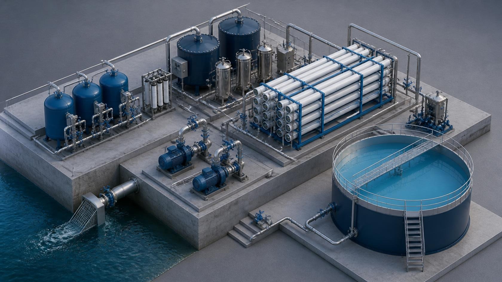
The process the Designer holds, as a projection of its own model
Engine reference case · not a screenshot
This is a seawater reverse-osmosis train drawn by the same process library the Designer configures: the node kinds, the stream roles and the stage order are the real ones. Every figure below is the engine’s own reference case rather than an illustration, and the interactive Plant Designer will redraw it for the numbers you state.
EngiMetric Arena
Engineering challenges you can defend
Not a quiz. Each Arena challenge is a real engineering problem — a review finding, a design decision, a diagnosis, a trade-off — graded by the same authoritative engines that power the calculators. Wrong answers get the reasoning, not just a mark, and every challenge states what it does not establish.
No account, no sign-up, and nothing stored on a server. Pick up a challenge, work it, and carry the answer into the full tool when you want to go further.
6 challenges published
Quick Challenge
How many RO elements can you actually buy?
The membrane area you need is not the number of elements you can procure. Work out how many elements a real vessel array must contain.
Open challengeSpot the Error
Review this RO energy calculation: the credit is missing
A designer has issued an energy figure for a seawater RO plant with an energy recovery device fitted. Identify the mistake in the review.
Open challengeEngineering verticals
Three bodies of engineering, at three depths.
A vertical is a body of engineering with its own tools and its own process — not a brand label. What each one models today is stated, including where it stops.
Water & Desalination
Primary engineering vertical
Desalination plant design, RO, pretreatment, water analysis and hydraulics, carried through equipment, schedule, BOQ and report.
- Reverse Osmosis (RO)
- Desalination Systems
- Water Treatment
- Water Quality & Chemistry
- Hydraulics & Pumping
58 live tools, including the Plant Designer and treatment train.
Explore Water & DesalinationWastewater
Emerging vertical
Biological process sizing, starting with the aeration basin. The basin loop closes on what you state, and reports what it cannot close.
- Activated Sludge
1 live tool. No treatment train or stream model yet — those are future work, not planned features presented as existing.
Explore WastewaterConstruction
Secondary engineering vertical
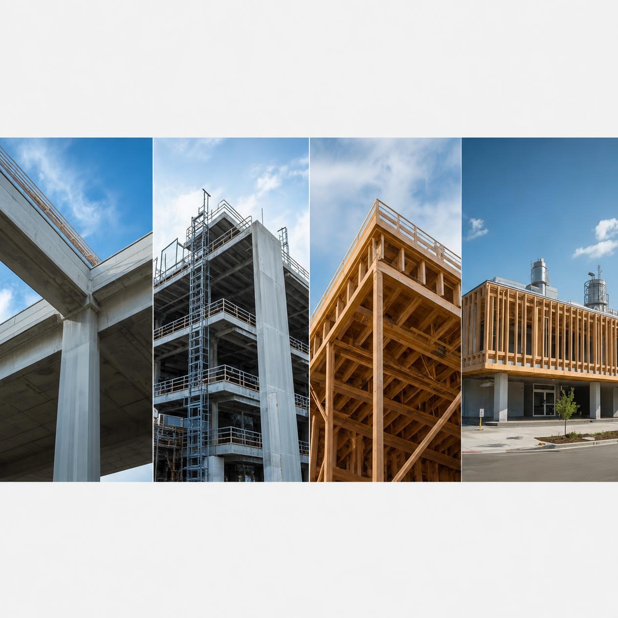
Concrete, reinforcement, quantity takeoff, earthwork, estimation and site engineering.
- Concrete Engineering
- Rebar & Reinforcement
- Masonry & Blockwork
- Earthwork & Excavation
- Stormwater & Drainage
91 live tools across 27 categories.
Explore ConstructionGuided workflows
Follow a flow, not a single formula.
Each path chains real calculation outputs in the order an engineer would run them. Every step opens the tool that produces its input.
RO System Analysis
Follow a membrane system from feedwater to design review, one calculation at a time.
- Feedwater
- 1 Recovery
- 2 Mass Balance
- 3 Permeate / Concentrate
- 4 Osmotic Pressure
- 5 Scaling Risk
- 6 Design Review
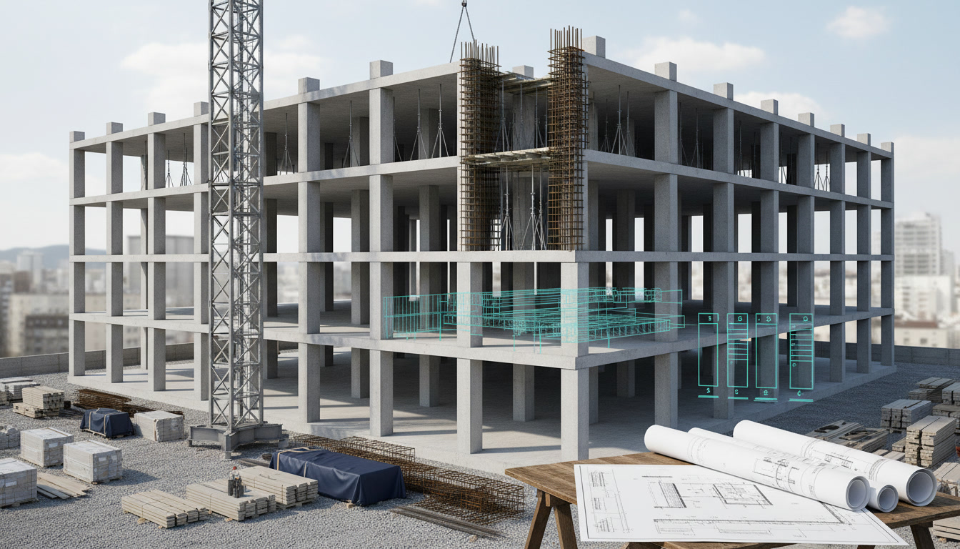
Concrete Engineering Workflow
From structure inputs to material quantities and site documentation.
- Project Input
- 1 Volume
- 2 Mix / Quantity
- 3 Rebar
- 4 Material Quantities
- Site Documentation
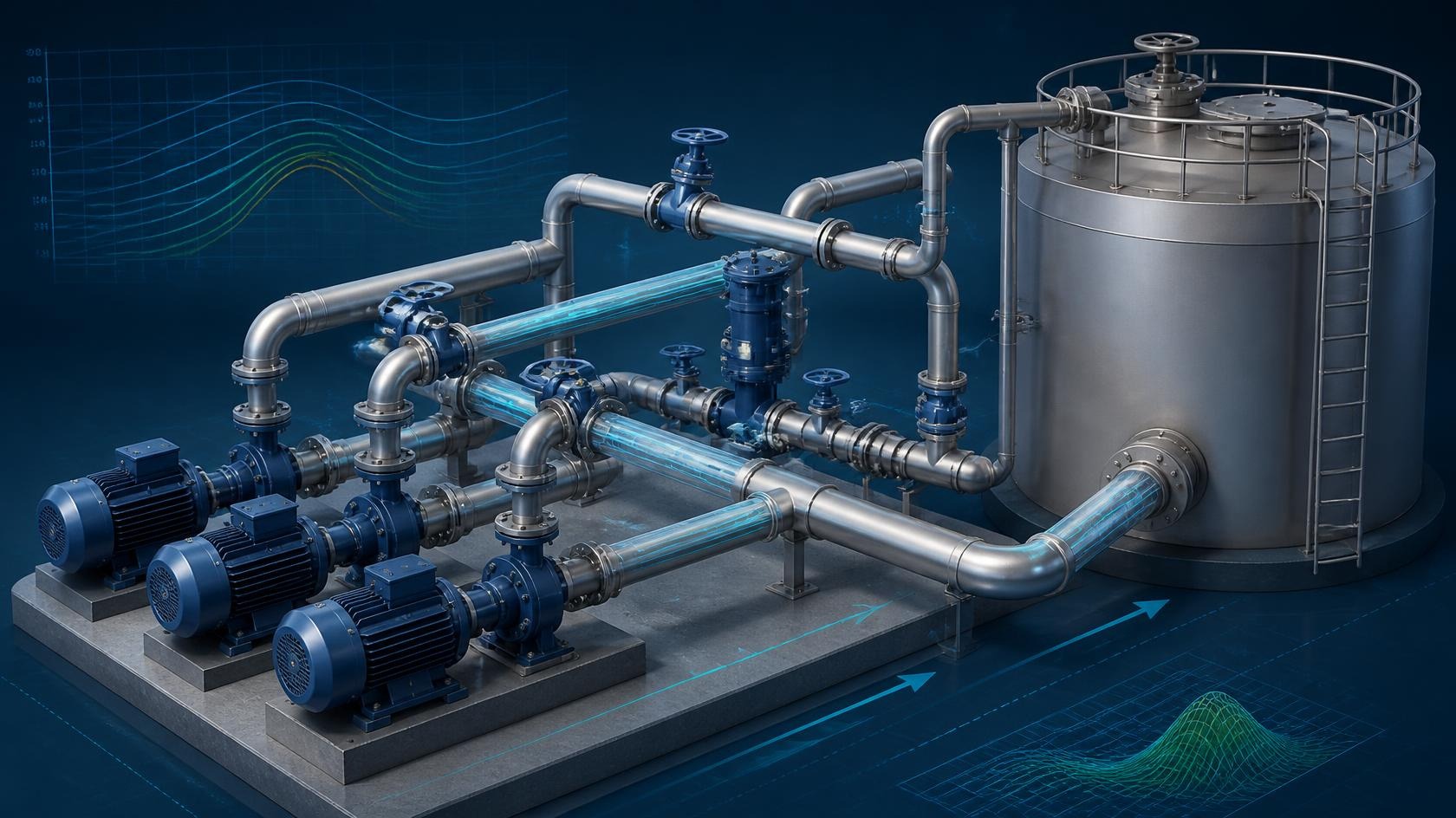
Hydraulics System Design
From flow requirement to sized line, checks, total dynamic head and pump power — one workflow.
Treatment Train: UF → NF → RO
Connect membrane stages into one train: a value moves only through a validated stream port, conversions are named, and the stages downstream recalculate automatically.
Learn & resources
The part of the platform that explains itself.
Every engine here is inspectable — the formula, its assumptions and its limits are written down, not buried.

Understand
Workspace
The design keeps itself.
Run a tool or the Plant Designer, save the run, collect it into a project, and draft a report. Everything is stored locally in this browser — no account, no cloud sync, and nothing leaves your device unless you export it.
- Run a tool or the Plant Designer
- Save the run with its inputs
- Collect runs into a project
- Reuse inputs across tools
- Track revisions
- Export CSV / Markdown / print
- RO Scaling Risk & Pretreatment→
Saved calculation · can reopen inputs
- Concrete Volume & Pre-Mix Quantities→
Saved calculation · can reload inputs
- Site-Ready Field Sheet→
Print / WhatsApp / CSV from any calculation
Engineering tools
Start from the duty, not from the calculator.
149 live engines across three verticals. Grouped by the job they do, so you can find the tool for a duty rather than the tool for a formula you already know.
Assess the feed
4Is this water treatable at all, and at what load?
Size a membrane train
7Recovery, stages, passes, elements and pressure vessels.
Protect the membranes
5Pretreatment, scaling and cartridge filtration.
Dose and disinfect
7Chemical duty and the contact time it needs.
Move the water
7Flow, head and power for the duty you just sized.
Size a biological basin
1Aeration volume, F/M, SRT and oxygen demand.
Quantify a structure
7Concrete, reinforcement, earthwork and quantities.
Size the equipment and its schedule
2Vessel, pump and tank sizing for the duty you derived.
Account for the reject stream
1Brine volume, salt load and the disposal constraint.
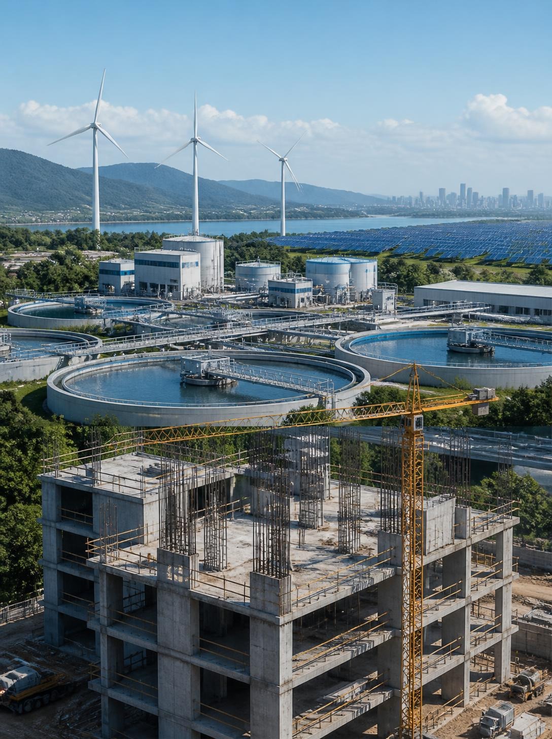
Bring your own numbers. The platform will not replace them.
Every engine here takes your stated basis and shows you what it derived from it, what it could not close, and what still needs an engineer's judgement. Free to use, and yours to check.
This calculator provides preliminary engineering estimates for informational and planning purposes. Actual reverse osmosis / engineering system performance depends on site conditions, feed-water chemistry, membrane characteristics, operating pressure, temperature, recovery limits, fouling/scaling potential, and system design. Verify results using project-specific data, manufacturer projections, and applicable engineering standards before final design or operation.